24.6 I2C MASTER MODE
Master mode is enabled by setting and clearing the appropriate SSPM bits in the SSPxCON1 register and by setting the SSPEN bit.
마스터 모드는 SSPxCON1레지스터의 적절한 SSPM 비트들을 셋/클리어 시켜서 활성화 시키고 SSPEN비트를 셋 시켜서 설정된다.
In Master mode, the SDAx and SCKx pins must be configured as inputs.
마스터 모드에서 SDAx와 SCKx핀은 입력으로 설정해야한다.
The MSSP peripheral hardware will override the output driver TRIS controls when necessary to drive the pins low.
MSSP 장치 하드웨어는 판이 Low가 되어야할 때 출력 TRIS 제어를 활용한다.
Master mode of operation is supported by interrupt generation on the detection of the Start and Stop conditions.
동작의 마스터 모드는 Start, Stop 조건 확인시 인터럽트를 활용한다.
The Stop (P) and Start (S) bits are cleared from a Reset or when the MSSPx module is disabled.
Stop(P), Start(S) 비트는 리셋 또는 MSSPx모듈의 비활성화 시 클리어 된다.
Control of the I2C bus may be taken when the P bit is set, or the bus is Idle.
I2C 버스의 제어는 P비트가 셋 되었거나 버스가 Idle 상태일 때 얻어지게 된다.
In Firmware Controlled Master mode, user code conducts all I2C bus operations based on Start and Stop bit condition detection.
펌웨어로 제어되는 마스터 모드에서, 사용자 코드는 모든 Start/Stop 비트 조건 확인에 기초를 둔 I2C 버스 동작으로 이루어진다.
Start and Stop condition detection is the only active circuitry in this mode.
이 모드에서 Start/Stop 조건 확인은 유일한 활성회로이다.(?)
All other communication is done by the user software directly manipulating the SDAx and SCLx lines.
다른 모든 통신은 사용자 소프트웨어로 직접 SDAx, SCLx 라인을 관리한다.
The following events will cause the SSPx Interrupt Flag bit, SSPxIF, to be set (SSPx interrupt, if enabled):
다음 이벤트들은 SSPx 인터럽트 플래그 비트(SSPxIF)를 발생시킨다.(SSPx 인터럽ㅌ, 활성화 되어 있다면)다음
• Start condition detected 시작 조건 검출
• Stop condition detected 정지 조건 검출
• Data transfer byte transmitted/received 바이트 데이터 전송/수신
• Repeated Start generated 재시작 발생
Note 1: The MSSPx module, when configured in I2C Master mode, does not allow queuing of events.
MSSPx 모듈이 I2C 마슽 모드로 설정되었을 때 이벤트 대기를 허용하지 않는다.
For instance, the user is not allowed to initiate a Start condition and immediately write the SSPxBUF register to initiate transmission before the Start condition is complete.
예를 들어 사용자는 시작 조건을 초기화 하고 시작 조건이 완성되기 전에 바로 SSPxBUF 레지스터에 전송데이터를 쓰지 못한다.
In this case, the SSPxBUF will not be written to and the WCOL bit will be set, indicating that a write to the SSPxBUF did not occur.
이 경우, SSPxBUF는 쓰여지지 않을 것이고, WCOL 비트가 셋 될 것이다. 이것은 SSPxBUF에 쓰기동작이 수행되지 않았음을 표시한다.
2: Master mode suspends Start/Stop detection when sending the Start/Stop condition by means of the SEN/PEN control bits.
마스터 모드는 SEN/PEN 제어 비트를 통해 시작/중지 조건을 보낼 때 시작/중지 감지를 중단한다.
The SSPxIF bit is set at the end of the Start/Stop generation when hardware clears the control bit.
하드웨어가 제어비트를 클리어 시킬 때, SSPxIF 비트는 Start/Stop 생성의 끝에 셋 된다.
24.6.1 I2C MASTER MODE OPERATION
The master device generates all of the serial clock pulses and the Start and Stop conditions.
마스터 장비는 시리얼 클럭 펄스, Start/Stop 조건을 발생시킨다.
A transfer is ended with a Stop condition or with a Repeated Start condition.
전송은 Stop 또는 재시작 조건으로 종료된다.
Since the Repeated Start condition is also the beginning of the next serial transfer, the I2C bus will not be released.
재시작 조건은 다음 시리얼 전송의 시작이기 때문에 I2C 버스는 놓여지지 않는다.
In Master Transmitter mode, serial data is output through SDAx, while SCLx outputs the serial clock.
마스터 전송 모드에서, 시리얼 데이터는 SDAx, 시리얼 클럭은 SCLx에서 출력된다.
The first byte transmitted contains the slave address of the receiving device (seven bits) and the Read/Write (R/W) bit.
첫번째 전송되는 바이트는 수신장치의 슬레이브 주소(7비트)와 R/W 비트를 가지고있다.
In this case, the R/W bit will be logic ‘0’.
이 경우 R/W 비트는 0이다.
Serial data is transmitted eight bits at a time.
시리얼 데이터는 한 번에 8비트가 전송된다.
After each byte is transmitted, an Acknowledge bit is received.
각 바이트가 전송되고난 뒤에 Acknowledge 비트가 수신된다.
Start and Stop conditions are output to indicate the beginning and the end of a serial transfer.
Start, Stop 조건들은 시리얼 전송의 시작과 끝을 표시하기 위해 출력된다.
In Master Receive mode, the first byte transmitted contains the slave address of the transmitting device (seven bits) and the R/W bit.
마스터 수신 모드에서 첫 바이트는 전송 장치의 슬레이브 주소와 R/W를 포함한다.
In this case, the R/W bit will be logic ‘1’.
이 경우 R/W 비트는 1이다.
Thus, the first byte transmitted is a 7-bit slave address followed by a ‘1’ to indicate the receive it.
그러므로, 첫 바이트는 7비트의 슬레이브 주소와 수신을 표시하는 1이 따라온다.
Serial data is received via SDAx, while SCLx outputs the serial clock.
SCLx가 시리얼 클럭을 출력하는 동안 시리얼 데이터는 SDAx를 통해 수신된다.
Serial data is received eight bits at a time.
시리얼 데이터는 한 번에 8비트가 수신된다.
After each byte is received, an Acknowledge bit is transmitted.
각 바이트들이 수신되고 난 뒤 Acknowledge 비트가 전송된다.
Start and Stop conditions indicate the beginning and end of transmission.
Start/Stop 조건들은 전송의 시작과 끝을 표시한다.
A Baud Rate Generator is used to set the clock frequency output on SCLx.
Baud Rate 발생기는 SCLx에 클럭 주파수 출력을 설정하는데 사용된다.
See Section 24.7 “Baud Rate Generator” for more details.
추가 자세한 내용은 24.7 Baud Rate Generator를 확인하라.
24.6.2 CLOCK ARBITRATION
Clock arbitration occurs when the master, during any receive, transmit or Repeated Start/Stop condition, releases the SCLx pin (SCLx allowed to float high). hen the SCLx pin is allowed to float high, the Baud Rate Generator (BRG) is suspended from counting until the SCLx pin is actually sampled high. When the SCLx pin is sampled high, the Baud Rate Generator is reloaded with the contents of SSPxADD<7:0> and begins counting. This ensures that the SCLx high time ill always be at least one BRG rollover count in the event that the clock is held low by an external device (Figure 24-25).

24.6.3 WCOL STATUS FLAG
If the user writes the SSPxBUF when a Start, Restart, Stop, Receive or Transmit sequence is in progress, the WCOL bit is set and the contents of the buffer are unchanged (the write does not occur). Any time the WCOL bit is set, it indicates that an action on SSPxBUF was attempted while the module was not Idle. Note: Because queuing of events is not allowed, writing to the lower five bits of SSPxCON2 is disabled until the Start condition is complete.
24.6.4 I2C MASTER MODE START CONDITION TIMING
To initiate a Start condition, the user sets the Start Enable bit, SEN bit of the SSPxCON2 register. If the SDAx and SCLx pins are sampled high, the Baud Rate Generator is reloaded with the contents of SSPxADD<7:0> and starts its count. If SCLx and DAx are both sampled high when the Baud Rate Generator times out (TBRG), the SDAx pin is driven low. The action of the SDAx being driven low while SCLx is high is the Start condition and causes the S bit of the SSPxSTAT1 register to be set. Following this, the Baud Rate Generator is reloaded with the contents of SSPxADD<7:0> and resumes its count. When the Baud Rate Generator times out (TBRG), the SEN bit of the SSPxCON2 register will be automatically leared by hardware; the Baud Rate Generator is suspended, leaving the SDAx line held low and the Start condition
Note 1: If, at the beginning of the Start condition, the SDAx and SCLx pins are already sampled low, or if during the Start condition, the SCLx line is sampled low before the SDAx line is driven low, a bus collision occurs. The Bus Collision Interrupt Flag, BCLxIF, is set, the Start condition is borted and the I2C module is reset into its Idle state. 2: The Philips I2C Specification states that a bus collision cannot occur on a Start.

24.6.5 I2C MASTER MODE REPEATED START CONDITION TIMING
A Repeated Start condition occurs when the RSEN bit of the SSPxCON2 register is programmed high and the Master state machine is no longer active. When the RSEN bit is set, the SCLx pin is asserted low. When the SCLx pin is sampled low, the Baud Rate Generator is oaded and begins counting. The SDAx pin is released (brought high) for one Baud Rate Generator count (TBRG). When the Baud Rate Generator times out, if SDAx is sampled high, the SCLx pin will be deasserted (brought high). When SCLx is sampled high, the Baud Rate Generator is reloaded and begins counting. SDAx and SCLx must be sampled high for one TBRG. This action is then followed by assertion of the SDAx pin (SDAx = 0) for one TBRG while SCLx is high. SCLx is asserted low. Following this, the RSEN bit of the SPxCON2 egister will be automatically cleared and the Baud Rate Generator will not be reloaded, leaving the SDAx pin held low. As soon as a Start condition is detected on the SDAx and SCLx pins, the S bit of the SSPxSTAT register will be set. The SSPxIF bit will not be set until the Baud Rate Generator has timed out.
Note 1: If RSEN is programmed while any other event is in progress, it will not take effect.
2: A bus collision during the Repeated Start condition occurs if:
• SDAx is sampled low when SCLx goes from low-to-high.
• SCLx goes low before SDAx is asserted low. This may indicate that another master is attempting to transmit a data ‘1’.

24.6.6 I2C MASTER MODE TRANSMISSION
Transmission of a data byte, a 7-bit address or the other half of a 10-bit address is accomplished by simply writing a value to the SSPxBUF register. This action will set the Buffer Full flag bit, BF, and allow the Baud Rate enerator to begin counting and start the next transmission. Each bit of address/data will be shifted out onto the SDAx pin after the falling edge of SCLx is asserted. SCLx is held low for one Baud Rate Generator rollover count (TBRG). Data should be valid before SCLx is released high. When the SCLx pin is released high, it is held that way for TBRG. The data on the SDAx pin must remain stable for that duration and some hold time after the next falling edge of SCLx. After the eighth bit is shifted out (the falling edge of the eighth clock), the BF flag is cleared and the master releases SDAx. This allows the slave device being addressed to respond with an ACK bit during the ninth bit time if an address match occurred, or if data was received properly. The status of ACK is written into the ACKSTAT bit on the rising edge of the ninth clock. If the master receives an Acknowledge, the Acknowledge Status bit, ACKSTAT, is cleared. If not, the bit is set. After the ninth clock, the SSPxIF bit is set and the master clock (Baud Rate Generator) is suspended until the next data byte is loaded into the SSPxBUF, leaving SCLx low and SDAx unchanged (Figure 24-27). After the write to the SSPxBUF, each bit of the address will be shifted out on the falling edge of SCLx until all seven address bits and the R/W bit are completed. On the falling edge of the eighth clock, the master will release the SDAx pin, allowing the slave to respond with an Acknowledge. On the falling edge of the ninth clock, the master will sample the SDAx pin to see if the address was recognized by a slave. The status of the ACK bit is loaded into the ACKSTAT Status bit of the SSPxCON2 register. Following the falling edge of the ninth clock transmission of the address, the SSPxIF is set, the BF flag is cleared and the Baud Rate Generator is turned off until another write to the SSPxBUF takes place, holding SCLx low and allowing SDAx to float.
24.6.6.1 BF Status Flag In Transmit mode, the BF bit of the SSPxSTAT register is set when the CPU writes to SSPxBUF and is cleared when all eight bits are shifted out.
24.6.6.2 WCOL Status Flag If the user writes the SSPxBUF when a transmit is already in progress (i.e., SSPxSR is still shifting out a data byte), the WCOL bit is set and the contents of the buffer are unchanged (the write does not occur). WCOL must be cleared by software before the next transmission.
24.6.6.3 ACKSTAT Status Flag
In Transmit mode, the ACKSTAT bit of the SSPxCON2 egister is cleared when the slave has sent an Acknowledge
(ACK = 0) and is set when the slave does not Acknowledge (ACK = 1). A slave sends an Acknowledge when it has recognized its address (including a general call), or when the slave has properly receivedits data.
24.6.6.4 Typical transmit sequence:
1. The user generates a Start condition by setting the SEN bit of the SSPxCON2 register.
2. SSPxIF is set by hardware on completion of the Start.
3. SSPxIF is cleared by software.
4. The MSSPx module will wait the required start time before any other operation takes place.
5. The user loads the SSPxBUF with the slave address to transmit.
6. Address is shifted out the SDAx pin until all eight bits are transmitted. Transmission begins as
soon as SSPxBUF is written to.
7. The MSSPx module shifts in the ACK bit from the slave device and writes its value into the
ACKSTAT bit of the SSPxCON2 register.
8. The MSSPx module generates an interrupt at the end of the ninth clock cycle by setting the
SSPxIF bit.
9. The user loads the SSPxBUF with eight bits of data.
10. Data is shifted out the SDAx pin until all eight bits are transmitted.
11. The MSSPx module shifts in the ACK bit from the slave device and writes its value into the ACKSTAT bit of the SSPxCON2 register.
12. Steps 8-11 are repeated for all transmitted data bytes.
13. The user generates a Stop or Restart condition by setting the PEN or RSEN bits of the SSPxCON2 register. Interrupt is generated once the Stop/Restart condition is complete.

24.6.7 I2C MASTER MODE RECEPTION
Master mode reception is enabled by programming the Receive Enable bit, RCEN bit of the SSPxCON2 register.
Note: The MSSPx module must be in an Idle state before the RCEN bit is set or the RCEN bit will be disregarded.
The Baud Rate Generator begins counting and on each rollover, the state of the SCLx pin changes (high-to-low/low-to- high) and data is shifted into the SSPxSR. After the falling edge of the eighth clock, the receive enable flag is automatically cleared, the contents of the SSPxSR are loaded into the SSPxBUF, the BF flag bit is set, the SSPxIF flag bit is set and the Baud Rate Generator is suspended from counting, holding SCLx low. The MSSPx is now in Idle state awaiting the next command. When the buffer is read by the CPU, the BF flag bit is automatically cleared. The user can then send an Acknowledge bit at the end of reception by setting the Acknowledge Sequence Enable, ACKEN bit of the SSPxCON2 register.
24.6.7.1 BF Status Flag In receive operation, the BF bit is set when an address or data byte is loaded into SSPxBUF from SSPxSR. It is cleared when the SSPxBUF register is read.
24.6.7.2 SSPOV Status Flag In receive operation, the SSPOV bit is set when eight bits are received into the SSPxSR and the BF flag bit is already set from a previous reception.
24.6.7.3 WCOL Status Flag If the user writes the SSPxBUF when a receive is already in progress (i.e., SSPxSR is still shifting in a data byte), the WCOL bit is set and the contents of the buffer are unchanged (the write does not occur).
24.6.7.4 Typical Receive Sequence
1. The user generates a Start condition by setting the SEN bit of the SSPxCON2 register.
2. SSPxIF is set by hardware on completion of the tart.
3. SSPxIF is cleared by software.
4. User writes SSPxBUF with the slave address to transmit and the R/W bit set.
5. Address is shifted out the SDAx pin until all eight bits are transmitted. Transmission begins as soon as SSPxBUF is written to.
6. The MSSPx module shifts in the ACK bit from the slave device and writes its value into the ACKSTAT bit of the SSPxCON2 register.
7. The MSSPx module generates an interrupt at the end of the ninth clock cycle by setting the SSPxIF bit.
8. User sets the RCEN bit of the SSPxCON2 register and the Master clocks in a byte from the slave.
9. After the eighth falling edge of SCLx, SSPxIF and BF are set.
10. Master clears SSPxIF and reads the received byte from SSPxUF, clears BF.
11. Master sets ACK value sent to slave in ACKDT bit of the SSPxCON2 register and initiates the ACK by setting the ACKEN bit.
12. Masters ACK is clocked out to the Slave and SSPxIF is set.
13. User clears SSPxIF.
14. Steps 8- 3 are repeated for each eceived byte from the slave.
15. Master sends a not ACK or Stop to end communication.

24.6.8 ACKNOWLEDGE SEQUENCE TIMING
An Acknowledge sequence is enabled by setting the Acknowledge Sequence Enable bit, ACKEN bit of the SSPxCON2 register. When this bit is set, the SCLx pin is pulled low and the contents of the Acknowledge data bit are presented on the SDAx pin. If the user wishes to generate an Acknowledge, then the ACKDT bit should be cleared. If not, the user should set the ACKDT bit before starting an Acknowledge sequence. The Baud
Rate Generator then counts for one rollover period (TBRG) and the SCLx pin is deasserted (pulled high).
When the SCLx pin is sampled high (clock arbitration), the Baud Rate Generator counts for TBRG. The SCLx pin
is then pulled low. Following this, the ACKEN bit is automatically cleared, the Baud Rate Generator is turned off
and the MSSPx module then goes into Idle mode(Figure 24-29).
24.6.8.1 WCOL Status Flag
If the user writes the SSPxBUF when an Acknowledge sequence is in progress, then the WCOL bit is set and
the contents of the buffer are unchanged (the write does not occur).
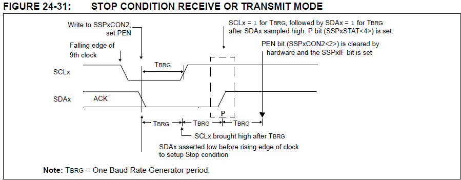
24.6.9 STOP CONDITION TIMING
A Stop bit is asserted on the SDAx pin at the end of a receive/transmit by setting the Stop Sequence Enable
bit, PEN bit of the SSPxCON2 register. At the end of a receive/transmit, the SCLx line is held low after the
falling edge of the ninth clock. When the PEN bit is set, the master will assert the SDAx line low. When the
SDAx line is sampled low, the Baud Rate Generator is reloaded and counts down to ‘0’. When the Baud Rate
Generator times out, the SCLx pin will be brought high and one TBRG (Baud Rate Generator rollover count)
later, the SDAx pin will be deasserted. When the SDAx pin is sampled high while SCLx is high, the P bit of the
SSPxSTAT register is set. A TBRG later, the PEN bit is cleared and the SSPxIF bit is set (Figure 24-30).
24.6.9.1 WCOL Status Flag
If the user writes the SSPxBUF when a Stop sequence is in progress, then the WCOL bit is set and the
contents of the buffer are unchanged (the write does not occur).

'PIC' 카테고리의 다른 글
| PIC16F1497 + I2C (0) | 2025.04.25 |
|---|---|
| PIC16F1947 - I2C (0) | 2025.01.20 |
| PIC16F1947 - PWM(Enhanced Mode) (1) | 2025.01.16 |
| PIC16F1947 - HFINTOSC (0) | 2025.01.16 |
| PIC IO PORT Test (0) | 2022.12.23 |

