PIC16F1947 - I2C
24.3 I2C MODE OVERVIEW
The Inter-Integrated Circuit Bus (I²C) is a multi-master serial data communication bus.
상호집적회로버스( I²C, 번역보다는 그냥 I²C로 부르는 것이 더 나을 듯)는 다중 마스터 시리얼 통신 버스이다. (마스터를 여러개 만들 수 있다는 얘기)
Devices communicate in a master/slave environment where the master devices initiate the communication.
장치는 마스터 장치가 통신을 시작하는 마스터/슬레이브환경에서의 통신을 한다.(이건 뭐 말을 이렇게 해 뒀어?)
A Slave device is controlled through addressing.
슬레이브 장치는 어드레싱을 통해 제어 된다
The I2C bus specifies two signal connections:
I2C 버스는 두 개의 특정 신호 연결을 사용한다.
• Serial Clock (SCLx) 클럭
• Serial Data (SDAx) 데이터
Figure 24-2 and Figure 24-3 show the block diagrams of the MSSPx module when operating in I2C mode.
그림 24-2, 24-3은 I2C 모드로 동작하는 MSSPx 모듈의 블럭 다이어그램이다.
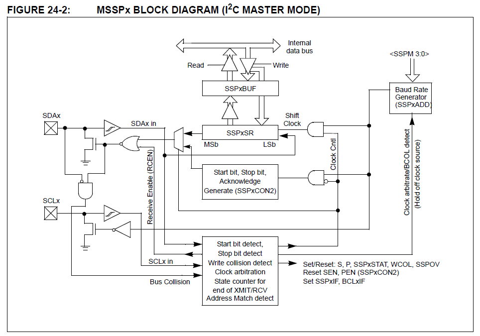
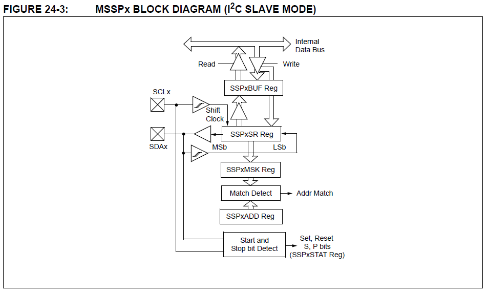
Both the SCLx and SDAx connections are bidirectional open-drain lines, each requiring pull-up resistors for the supply voltage.
SCLx, SDAx는 양방향의 오픈드레인 라인에 연결되고, 각각 전원에 대해 풀업저항이 필요하다.
Pulling the line to ground is considered a logical zero and letting the line float is considered a logical one.
접지에 라인을 연결하는 것은 논리 zero이고, 라인을 플로팅 상태로 두면 논리 1로 생각된다.
Figure 24-11 shows a typical connection between two processors configured as master and slave devices.
그림 24-11은 두 개의 프로세서 사이를 마스터와 슬레이브 장치로 연결하는 일반적인 예를 본여준다.

The I2C bus can operate with one or more master devices and one or more slave devices.
I2C 버스는 하나 또는 다중 마스터 장치와 하나 또는 다중 슬레이브 장치들과 함께 동작 할 수 있다.
There are four potential modes of operation for a given device:
장치는 4가지의 동작 모드를 갖는다..
• Master Transmit mode 마스터 전송모드
(master is transmitting data to a slave) 마스터가 데이터를 슬레이브로 보낸다.
• Master Receive mode 마스터 수신 모드
(master is receiving data from a slave) 마스터가 슬레이브로부터 데이터를 받는다.
• Slave Transmit mode 슬레이브 전송 모드
(slave is transmitting data to a master) 슬레이브가 데이터를 마스터에 전송한다.
• Slave Receive mode 슬레이브 수신 모드
(slave is receiving data from the master)슬레이브가 마스터로부터 데이터를 수신한다.
To begin communication, a master device starts out in Master Transmit mode.
통신을 시작하기 위해서는, 마스터 장치가 마스터 전송 모드에서 시작해야한다.
The master device sends out a Start bit followed by the address byte of the slave it intends to communicate with.
마스터 장치가 시작 비트 뒤에 통신을 할 슬레이브의 어드레스를 이어서 송신한다.
This is followed by a single Read/Write bit, which determines whether the master intends to transmit to or receive data from the slave device.
이것 뒤에 read/write의 1 비트를 전송한다. 이것은 마스터가 슬레이브로부터 또는 슬레이브에게 데이터를 전송 또는 수신하겠다는 것을 결정한다.
If the requested slave exists on the bus, it will respond with an Acknowledge bit, otherwise known as an ACK.
버스 내에 요청 받은 슬레이브가 있다면, ACK 비트로 응답할 것이다. (ACK)
The master then continues in either Transmit mode or Receive mode and the slave continues in the complement, either in Receive mode or Transmit mode, respectively.
그리고, 마스터는 송신 또는 수신 모드로 동작할 것이고 슬레이브는 수신 모드 또는 송신모드에서 각각 보완을 계속한다.(???)
A Start bit is indicated by a high-to-low transition of the SDAx line while the SCLx line is held high.
START 비트는 SCL이 HIGH인 상태에서 SDA가 High에서 Low로 변환하는 것으로 표시된다.
Address and data bytes are sent out, Most Significant bit (MSb) first.
어드레스와 데이터 바이트는 MSB 비트부터 송신된다.
The Read/Write bit is sent out as a logical one when the master intends to read data from the slave, and is sent out as a logical zero when it intends to write data to the slave.
읽기/쓰기 비트는 마스터가 슬레이브로부터 데이터를 읽고자 할 때는 논리 1, 슬레이브에 데이터를 쓰려고 할 경우에는 논리 0이 전송된다.
The Acknowledge bit (ACK) is an active-low signal, which holds the SDAx line low to indicate to the transmitter that the slave device has received the transmitted data and is ready to receive more.
ACK 비트는 Active-Low 신호이고, SDAx라인을 Low로 만들어 송신장치에, 슬레이브 장치가 송신된 데이터를 받았고 더 받을 준비가 되었다는 것을 표시해준다.
The transition of a data bit is always performed while the SCLx line is held low.
데이터 비트의 전송은 항상 SCLx라인이 Low일때 동작된다.
Transitions that occur while the SCLx line is held high are used to indicate Start and Stop bits.
SCLx 라인이 High일 때 발생한 전송은 Start/Stop 비트를 표시한다.
If the master intends to write to the slave, then it repeatedly sends out a byte of data, with the slave responding after each byte with an ACK bit.
마스터가 슬레이브에 쓰기를 하려고하면, 데이터의 바이트들을 반복적으로 전송한다. 슬레이브는 각 바이트마다 ACK 비트로 응답한다.
In this example, the master device is in Master Transmit mode and the slave is in Slave Receive mode.
이 예에서는 마스터 장치가 마스터 전송모드이고 슬레이브가 슬레이브 수신 모드이면
If the master intends to read from the slave, then it repeatedly receives a byte of data from the slave, and responds after each byte with an ACK bit.
마스터가 슬레이브로부터 읽기를 수행하고자 한다면 슬레이브로부터 데이터 바이트를 각각 수신하게 되고 각 바이트 뒤에 ACK 비트로 응답한다.
In this example, the master device is in Master Receive mode and the slave is Slave Transmit mode.
이 예에서는 마스터 장치는 마스터 수신 모드이고, 슬레이브는 슬레이브 전송모드이다.
On the last byte of data communicated, the master device may end the transmission by sending a Stop bit.
데이터 통신의 마지막 바이트에서 마스터 장치는 Stop 비트를 전송하므로서 전송을 종료시킨다.
If the master device is in Receive mode, it sends the Stop bit in place of the last ACK bit.
만약 마스터 장치가 수신 모드이면, Stop 비트를 마지막 ACK 비트에 위치시킨다.
A Stop bit is indicated by a low-to-high transition of the SDAx line while the SCLx line is held high.
Stop 비트는 SCLx 라인이 High일 때 SDAx 라인이 Low에서 High로 변경되면 된다.
In some cases, the master may want to maintain control of the bus and re-initiate another transmission.
어떤 경우, 마스터는 버스를 유지 제어하기를 원하고, 다를 전송을 다시 초기화 하기도 한다.
If so, the master device may send another Start bit in place of the Stop bit or last ACK bit when it is in receive mode.
이럴 경우 수신 모드에서 마스터 장치는 Stop 비트의 자리또는 마지막 ACK 비트 자리에 Start 비트를 보낼 수도 있다.
The I2C bus specifies three message protocols:
I2C 버스의 세가지 특별한 메시지 프로토콜
• Single message where a master writes data to a slave. 마스터가 슬레이브에 쓰는 데이터인 단일 메시지
• Single message where a master reads data from a slave. 마스터가 슬레이브에서 읽는 데이터인 단일 메시지
• Combined message where a master initiates a minimum of two writes, or two reads, or a combination of writes and reads, to one or more slaves.
마스터가 하나 또는 그 이상의 슬레이브들에 최소 두 번 쓰기, 두 번 읽기, 또는 쓰기와 읽기의 복합 된 복합 메시지
When one device is transmitting a logical one, or letting the line float, and a second device is transmitting a logical zero, or holding the line low, the first device can detect that the line is not a logical one.
하나의 장치가 논리 1 을 전송하거나 라인을 float 상태로 만들고, 두 번째 장치가 논리 0을 전송하거나 라인을 Low로 만들면, 첫 번 째 장치는 라인이 논리 1이 아닌 것을 확인할 수 있다.
This detection, when used on the SCLx line, is called clock stretching.
SCLx라인을 사용할 때 이 확인을 클럭 스트레칭이라고 부른다.
Clock stretching gives slave devices a mechanism to control the flow of data.
클럭 스트레칭은 슬레이브 장치가 데이터 흐름을 제어할 수 있도록 해 준다.
When this detection is used on the SDAx line, it is called arbitration.
이 검출이 SDAx라인에 사용되면 이것을 Arbitration이라 한다.
Arbitration ensures that there is only one master device communicating at any single time.
Arbitration은 한 번에 하나의 마스터 장치만 통신할 수 있도록 해 준다.
24.3.1 CLOCK STRETCHING
When a slave device has not completed processing data, it can delay the transfer of more data through the process of clock stretching.
슬레이브 장치가 데이터 처리를 완료하지 못했을 때 클럭 스트레칭 동작을 통하여 추가적인 데이터 전송을 지연시킬 수 있다.
An addressed slave device may hold the SCLx clock line low after receiving or sending a bit, indicating that it is not yet ready to continue.
한 비트를 수신하거나 보내고 난 뒤에 주소지정된 슬레이브 장치는 SCLx 클럭 라인을 Low로 유지할 수 있다. 이것은 지속할 수 있는 준비가 아직 안되어 있음을 보여준다.
The master that is communicating with the slave will attempt to raise the SCLx line in order to transfer the next bit, but will detect that the clock line has not yet been released.
슬레이브와 통신을 하고 있는 마스터는 다음 비트를 전송하기 위해 SCLx 라인을 상승 시키려고 시도한다. 그러나 클럭이 아직 놓여지지 않았음을 검출 하게 된다.
Because the SCLx connection is open-drain, the slave has the ability to hold that line low until it is ready to continue communicating.
SCLx 연결은 Open-drain이기 때문에, 슬레이브는 통신이 준비 될 때 까지 Low 상태로 기다릴 수 있도록 유지시킬 수 있는 능력을 가지고 있다.
Clock stretching allows receivers that cannot keep up with a transmitter to control the flow of incoming data.
클럭 스트레칭은 수신데이터의 흐름을 제어하는 전송장치가 유지할 수 없는 것을 수신할 수 있도록 해준다.
24.3.2 ARBITRATION
Each master device must monitor the bus for Start and Stop bits.
각 마스터 장치는 시작과 정지 비트에 대해서 확인해야만한다.
If the device detects that the bus is busy, it cannot begin a new message until the bus returns to an Idle state.
장치는 버스가 사용중임을 확인하면, 버스가 다시 Idle 상태가 될 때 까지 새로운 메시지를 시작할 수 없다.
However, two master devices may try to initiate a transmission on or about the same time.
그러므로 두 마스터 장치가 전송을 위해 같은 시간에 초기화할 수도 있다.
When this occurs, the process of arbitration begins.
이 것이 발생했을 때 Arbitration의 동작이 시작 된다.
Each transmitter checks the level of the SDAx data line and compares it to the level that it expects to find.
각 전송 장치는 SDAx ㄷ이터 라인의 레벨을 확인하고, 그것을 확인이 되어야하는 레벨과 비교한다.
The first transmitter to observe that the two levels do not match, loses arbitration, and must stop transmitting on the SDAx line.
두 레벨이 서로 맞지 않음을 확인한 첫 번째 전송장치는 Arbitration을 잃게 되고, SDAx 라인에 전송하는 것을 정지해야한다.
For example, if one transmitter holds the SDAx line to a logical one (lets it float) and a second transmitter holds it to a logical zero (pulls it low), the result is that the SDAx line will be low.
예를 들어, 하나의 전송장치는 ADA 라인을 논리 1로 유지하고(float 상태로 둔다) 두 번째 전송장치는 논리 0으로 유지(Pull-down) 할 때, 결과는 SDAx 라인이 Low 상태가 된다.
The first transmitter then observes that the level of the line is different than expected and concludes that another transmitter is communicating.
첫 번 째 전송장치는 이후 라인의 레벨이 원하는 것과 틀리다는 것을 관찰하고 다른 전송장치가 통신을 할 수 있도록 해 준다.
The first transmitter to notice this difference is the one that loses arbitration and must stop driving the SDAx line.
이 틀림을 알아치린 첫 번 째 전송 장치는 Arbitration을 잃어버린 것이고 SDAx 라인을 사용하는 것을 정지해야한다.
If this transmitter is also a master device, it also must stop driving the SCLx line.
이 전송장치가 또한 마스터 장치이면, SCLx 라인을 사용하는 것을 또한 멈춰야한다.
It then can monitor the lines for a Stop condition before trying to reissue its transmission.
이것은 다른 전송을 만드는 것을 하기 전에 Stop 조건을 위해 라인을 확인할 수 있다.
In the meantime, the other device that has not noticed any difference between the expected and actual levels on the SDAx line continues with its original transmission.
그러는 동안 SDAx 라인의 실제 레벨과 필요한 레벨 사이의 차이점을 인식하지 못한 다른 장치는 기본 전송을 계속한다.
It can do so without any complications, because so far, the transmission appears exactly as expected with no other transmitter disturbing the message.
이것은 다른 문제 없이 동작할 수 있다. 왜냐하면 지금까지, 메시지를 방해하는 다른 송신기 없이 전송이 예상대로 정확하게 나타난다.
Slave Transmit mode can also be arbitrated, when a master addresses multiple slaves, but this is less common.
마스터가 다중 슬레이브를 지정하였을 때, 슬레이브 전송도 중재가 가능하다. 그러나 이것은 일반적이지 않은 경우이다.
If two master devices are sending a message to two different slave devices at the address stage, the master sending the lower slave address always wins arbitration.
두 마스터 장치가 어드레스 단계에서 두 개의 다른 슬레이브 장치에 메시지를 전송한다면, 낮은 슬레이브 주소를 전송한 마스터가 항상 중재에서 이긴다.
When two master devices send messages to the same slave address, and addresses can sometimes refer to multiple slaves, the arbitration process must continue into the data stage.
두 마스터 장치가 같은 슬레이브 어드레스에 동시에 메시지를 전송하고, 어드레스들은 때때로 여러 슬레이브에서 참조 될 때 중재 과정은 데이터 단계까지 계속 되어야 한다.
Arbitration usually occurs very rarely, but it is a necessary process for proper multi-master support.
중재는 드물게 발생하나 다중 마스터를 지원하기 위해서는 꼭 필요한 과정이다.
24.4 I2C Mode Operation
All MSSPx I2C communication is byte-oriented and shifts out MSb first.
모든 MSSPx I2C 통신은 바이트 단위이고 MSb부터 송신된다.
Six SFR registers and two interrupt flags interface the module with the PIC® microcontroller and user software.
6개의 SFR 레지스터들과 2개의 인터러트 플래그들이 모듈을 PIC® microcontroller 와 사용자 소프트웨어를 연결시킨다.
Two pins, SDAx and SCLx, are exercised by the module to communicate with other external I2C devices.
두 핀(SDAx, SCLx)은 다른 외부 I2C 장치와 통신을 하도록 모듈에 의해서 동작 되어진다.
24.4.1 BYTE FORMAT
All communication in I2C is done in 9-bit segments.
모든 I2C 통신은 9 비트로 이루어진다.
A byte is sent from a Master to a Slave or vice-versa, followed by an Acknowledge bit sent back.
마스터에서 슬레이브로 또는 반대로 전송되는 바이트 뒤에 ACK 비트 역으로 전송된다.
After the eighth falling edge of the SCLx line, the device outputting data on the SDAx changes that pin to an input and reads in an acknowledge value on the next clock pulse.
8개의 SCLx라인의 하강에지 뒤에, 장치는 SDAx에 데이터를 전송하는 것은 SDAx를 입력으로 변경시키고 다음 클럭 펄스에서 ACK 값을 익는다.
The clock signal, SCLx, is provided by the master.
클럭 신호 SCLx는 마스터에 의해서 제공된다.
Data is valid to change while the SCLx signal is low, and sampled on the rising edge of the clock.
SCLx 신호가 Low일 동안 변경된 데이터는 유효하고, 클럭 신호가 상승에지일 때 취득된다.
Changes on the SDAx line while the SCLx line is high define special conditions on the bus, explained below.
SCLx 라인이 High일 동안 SDAx 라인에서의 변화는 버스의 특별 조건들이고 아래에서 설명한다.
24.4.2 DEFINITION OF I2C TERMINOLOGY
here is language and terminology in the description of I2C communication that have definitions specific to I2C.
다음은 I2C에 특정한 정의를 가지고 있는 I2C 통신 설명의 언어 및 용어이다.
That word usage is defined below and may be used in the rest of this document without explanation.
이 단어의 사용은 아래에서 정의 되고 이 문서의 나머지 부분에서 설명없이 사용될 수 있다.
This table was adapted from the Philips I2C specification.
이 테이블은 Philips I2C 정의에서 채택되었다.
24.4.3 SDAx AND SCLx PINS
Selection of any I2C mode with the SSPEN bit set, forces the SCLx and SDAx pins to be open-drain.
SSPEN 비트가 설정된 I2C모드를 선택하면 SCLx와 SDAx 핀을 Open-drain이 된다.
These pins should be set by the user to inputs by setting the appropriate TRIS bits.
이 핀들은 TRIS 비트들을 적절하게 설정해서 사용자에 의해서 입력으로 설정되어야 한다.
Note: Data is tied to output zero when an I2C mode is enabled.
주의 : I2C 모드가 활성화 될 때 데이터는 0 출력으로 된다.
24.4.4 SDAx HOLD TIME
The hold time of the SDAx pin is selected by the SDAHT bit of the SSPxCON3 register.
SDAx 핀의 홀드 시간은 SSPxCON3레지스터의 SDAHT 비트에 의해 결정된다.
Hold time is the time SDAx is held valid after the falling edge of SCLx.
홀드타임은 SCLx의 하강에지 후 지속되는 SDAx 시간이다.
Setting the SDAHT bit selects a longer 300 ns minimum hold time and may help on buses with large capacitance.
SDAHT 비트를 설정하는 것은 300ns 이상의 최소 유지시간이 선택되고 정전 용량이 큰 버스에 도움이 될 수 있다.

24.4.5 START CONDITION
The I2C specification defines a Start condition as a transition of SDAx from a high to a low state while SCLx line is high.
I2C 사양에서는 시작 조건을 SCLx 라인이 High 상태에서 SDAx 가 High에서 Low로 상태가 변화하는 것으로 정의한다.
0A Start condition is always generated by the master and signifies the transition of the bus from an Idle to an Active state.
시작 조건은 항상 마스터에의해 생성되고, 버스가 Idle 상태에서 Active 상태로 변화하는 것을 표시한다.
Figure 24-10 shows waveforms for Start and Stop conditions.
그림 24-12은 시작과 정지 조건의 파형을 보여준다.
A bus collision can occur on a Start condition if the module samples the SDAx line low before asserting it low.
모듈이 Low를 출력하기 전에 SDAx 라인을 Low로 만들면 시작 조건에서 버스 충돌이 발생할 수 있다.
This does not conform to the I2C Specification that states no bus collision can occur on a Start.
이것은 시작 시 버스 충돌이 발생할 수 없다고 한 I2C 사양에 맞지 않는다.
24.4.6 STOP CONDITION
A Stop condition is a transition of the SDAx line from low-to-high state while the SCLx line is high.
정지 조건은 SCLx가 High일 때 SDAx가 Low에서 High로 상태변화가 있을 때이다.
Note: At least one SCLx low time must appear before a Stop is valid, therefore, if the SDAx line goes low then high again while the SCLx line stays high, only the Start condition is detected.
Stop 전에 적어도 하나의 SCLx이 Low인 시간이 나타나야 유효하다. 그러므로, SCLx가 High 일 때, SDAx 가 Low에서 High로 다시 간다면, 단지 시작 조건이 검출 된다.
24.4.7 RESTART CONDITION
A Restart is valid any time that a Stop would be valid.
재시작은 stop이 유효한 뒤에 언제든 유효하다.
A master can issue a Restart if it wishes to hold the bus after terminating the current transfer.
마스터는 현재 전송이 종료되고 난 뒤에 버스를 붙잡고 있기를 원한다면 재시작을 시킬 수 있다.
A Restart has the same effect on the slave that a Start would, resetting all slave logic and preparing it to clock in an address.
재시작은 시작과 같이 슬레이브에 동일한 효과를 갖는다. 모든 슬레이브 논리를 재설정하고 어드레스 클럭을 수신하도록 준비시킨다.
The master may want to address the same or another slave.
마스터는 같거다 다른 슬레이브의 주소를 지정하는 것을 원할 수 있다.
In 10- bit Addressing slave mode, a Restart is required for the master to clock data out of the addressed slave.
10비트 어드레싱 슬레이브 모드에서, 마스터가 지정된 슬레이브에서 데이터를 출력 시키기 위해 클럭을 인가하려면 재시작이 필요하다.
Once a slave has been fully addressed, matching both high and low address bytes, the master can issue a Restart and the high address byte with the R/W bit set.
슬레이브가 전체 어드레스를 수신하였을 때, 상/하위 어드레스 바이트가 맞다면, 마스터는 재시작을 시킬 수 있고, 상위 어드레스 바이트의 R/W 비트를 셋 시킬수 있다.
The slave logic will then hold the clock and prepare to clock out data.
슬레이브 로직은 이때 클럭을 잡은 상태에서 데이터 출력을 위한 클럭을 준비할 것이다.
After a full match with R/W clear in 10- it mode, a prior match flag is set and maintained.
10-bit 모드에서 R/W 까지 전체가 맞은 뒤에, 우선 순위 플래그가 셋 되고 관리된다.(?)
Until a Stop condition, a high address with R/W clear, or high address match fails.
Stop 조건 때 까지, R/W를 동반한 상위 어드레스는 지워지거나 상위어드레스가 맞지 않게 된다.(?)
24.4.8 START/STOP CONDITION INTERRUPT MASKING
The SCIE and PCIE bits of the SSPxCON3 register can enable the generation of an interrupt in Slave modes that do not typically support this function.
슬레이브모드에서 SSPxCON3 레지스터의 SCIE, PCIE 비트들은 인터럽트를 발생시킬 수 있다. 이 기능은 일반적으로 지원하지 않는다.?
Slave modes where interrupt on Start and Stop detect are already enabled, these bits will have no effect.
슬레이브 모드에서 시작, 정지가 발생할 때의 인터럽트는 이미 활성화 되어 있다. 이 비트들은 영향이 없다.

24.4.9 ACKNOWLEDGE SEQUENCE
The 9th SCLx pulse for any transferred byte in I2C is dedicated as an Acknowledge.
I2C에서 바이트 전송에 사용되는 9번째 SCLx 펄스는 Acknowledge에 사용된다.
It allows receiving devices to respond back to the transmitter by pulling the SDAx line low.
이것은 수신장치가 SDAx 라인을 Low로 잡아 둠으로써 송신장치에 응답을 보내는 것이다.
The transmitter must release control of the line during this time to shift in the response.
전송장치는 등답을 옮기기 위해서 이 시간동안 제어권을 놓아 둬어야 한다.
The Acknowledge (ACK) is an active-low signal, pulling the SDAx line low indicated to the transmitter that the device has received the transmitted data and is ready to receive more.
Acknowledge(ACK)는 Active Low 신호이다. SDAx 라인을 Low로 잡아 두는 것은 전송장치에서 수신장치가 전송된 데이터를 수신하였고, 추가 수신이 준비 됐다는 것을 알려준다.
The result of an ACK is placed in the ACKSTAT bit of the SSPxCON2 register.
ACK의 결과는 SSPxCON2 레지스터의 ACKSTAT 비트에 저장된다.
Slave software, when the AHEN and DHEN bits are set, allows the user to set the ACK value sent back to the transmitter.
슬레이브 소프트웨어에서, AHEN, DHEN 비트가 셋 되어 있다면, 사용자가 ACK 값을 전송장치에 보낼 수 있다.
The ACKDT bit of the SSPxCON2 register is set/cleared to determine the response.
SSPxCON2 레지스터의 ACKDT 비트는 응답을 결정하기 위해서 셋/클리어 될 수 있다.
Slave hardware will generate an ACK response if the AHEN and DHEN bits of the SSPxCON3 register are clear.
슬레이브 하드웨어는 SSPxCON3레지스터의 AHEN, DHEN 비트가 클리어 되어 있으면 ACK응답을 발생시킬 것이다.
An ACK will not be sent by the slave when an overflow condition is detected.
오버플로우 조건이 확인되면 슬레이브는 ACK를 보내지 않는다.
An overflow condition is defined by either the SSPxSTAT register bit BF being set, or by the SSPxCON1 register bit SSPOV being set.
오버플로우 조건은 SSPxSTAT 레지스터의 BF 비트가 셋 되어 있거나 SSPxCON1 레지스터의 SSPOV 비트가 셋 되면 결정된다.
When the module is addressed, after the eighth falling edge of SCLx on the bus, the ACKTIM bit of the SSPxCON3 register is set.
모듈이 주소지정이 되었을 때 SCLx의 8번째 하강 에지 후에 SSPxCON3 레지스터의 ACKTIM 비트가 셋 된다.
The ACKTIM bit indicates the acknowledge time of the active bus.
ACKTIM 비트는 활성화된 버스에 Acknowledge 시간을 표시해 준다.
The ACKTIM Status bit is only active when the AHEN bit or DHEN bit is enabled.
ACKTIM 상태비트는 AHEN, DHEN 비트가 활성화 될 때 동작한다.
24.5 I2C SLAVE MODE OPERATION The MSSPx
Slave mode operates in one of four modes selected in the SSPM bits of SSPxCON1 register. The modes can be divided into 7-bit and 10-bit Addressing mode. 10- it ddressing modes operate the same as 7-bit with some additional overhead for handling the larger addresses. Modes with Start and Stop bit interrupts operated the same as the other modes with SSPxIF additionally getting set upon detection of a Start, Restart, or Stop condition.
24.5.1 SLAVE MODE ADDRESSES
The SSPxADD register (Register 24- ) contains the Slave mode address. The first byte received after a Start or Restart condition is compared against the value stored in this register. If the byte matches, the value is loaded into the SSPxBUF register and an interrupt is generated. If the value does not match, the module goes idle and no indication is given to the software that anything happened. The SSPx Mask register (Register 24-5) affects the address matching process. See Section 24.5.9 “SSPx Mask Register” for more information.
24.5.1.1 I2C Slave 7-bit Addressing Mode
In 7- it Addressing mode, the LSb of the eceived data byte is ignored when determining if there is an address match.
24.5.1.2 I2C Slave 10-bit Addressing Mode
In 10-bit Addressing mode, the first received byte is compared to the binary value of ‘1 1 1 1 0 A9 A8 0’. A9 and A8 are the two MSb of the 10-bit address and stored in bits 2 and 1 of the SSPxADD register. After the acknowledge of the high byte, the UA bit is et and SCLx is held low until the user updates SSPxADD with the low address. The low address byte is clocked in and all eight bits are compared to the low address value in SSPxADD. Even if there is not an address match, SSPxIF and UA are set, and SCLx is held low until SSPxADD is updated to receive a high byte again. When SSPxADD is updated, the UA bit is cleared. This ensures the module is ready to receive the high address byte on the next communication. A high and low address match as a write request is required at the start of all 10-bit addressing communication. A transmission can be initiated by issuing a Restart once the slave is addressed, and clocking in the high address with the R/W bit set. The slave hardware will then acknowledge the read request and prepare to clock out data. This is only valid for a slave after it has received a complete high and low address byte match.